Friday, March 20, 2020

Initializing Application Processors on Windows

This post guides you to the journey of starting up application processors (APs) on Windows. This post can be read just for fun but can also help you make more sense of the INIT-SIPI-SIPI VM-exits sequence you have to handle when writing an UEFI hypervisor.

AP Initialization and Overview of Its Implementation


Before running any software code, hardware selects the processor that gets initialized and starts executing firmware code. This processor is called a bootstrap processor (BSP) and is basically the sole active processor until an operating system starts up the rest of the processors. 

Those non-BSP are called APs and are initialized by the BSP sending a sequence of inter processor interrupts (IPIs): INIT, Startup IPI, and the 2nd Startup IPI. This sequence is also referred to as INIT-SIPI-SIPI.

As noted in the previous post, a hypervisor that starts earlier than the operating system needs to handle VM-exists caused by those IPIs. But when that happen exactly? 

On Linux, this is relatively easy to find out. Searching "STARTUP IPI" in Linux source code or other developers' forums leads you to the implementation, smpboot.c. On Windows 10, this is done in HalpApicStartProcessor, called from kernel's KeStartAllProcessors, in short. The stack trace is shown below: 

00 hal!HalpApicStartProcessor
01 hal!HalpInterruptStartProcessor
02 hal!HalStartNextProcessor
03 nt!KeStartAllProcessors
04 nt!Phase1InitializationDiscard
05 nt!Phase1Initialization
06 nt!PspSystemThreadStartup
07 nt!KiStartSystemThread

Let us look into little more details on Windows 19H1 (18362.1.amd64fre.19h1_release.190318-1202) without Hyper-V enabled. To be clear, the execution path varies drastically if Hyper-V is enabled.

High Level Flow


KeStartAllProcessors captures various system register values with KxInitializeProcessorState, updates per processor book keeping data structures and calls HalStartNextProcessors for each registered processor one by one to start all of them. 

HalpInterruptStartProcessor builds stub code and temporal data structures required for APs to go through real-mode, 32 bit protected-mode, and long-mode, such as page tables, GDT, and IDT. HalpLowStub (that is PROCESSOR_START_BLOCK according to this talk by Alex Ionescu) is the address of where those are build and the very entry point of the AP. We will review the entry point code and how it goes up to the NT kernel. 

HalpInterruptStartProcessor, after the stub is built. executes HalpApicStartProcessor which is responsible for issuing the INIT-SIPI-SIPI sequence. Pseudo code of this function is shown below.

NTSTATUS HalpApicStartProcessor(     UINT64,     UINT32 LocalApicId,     UINT64,     UINT32 StartupIp     ) {     //     // Assert INIT, then de-assert it. INIT-deassert IPI is done only for backword     // compatibility.     // See: 10.4.7.4 Local APIC State After It Receives an INIT-Deassert IPI     //     HalpApicWriteCommand(LocalApicId, 0xC500); // APIC_INT_LEVELTRIG | APIC_INT_ASSERT | APIC_DM_INIT     KeStallExecutionProcessor(10u);
    HalpApicWriteCommand(LocalApicId, 0x8500); // APIC_INT_LEVELTRIG | APIC_DM_INIT     KeStallExecutionProcessor(200u);
    //     // Compute the SIPI message value and send it.     // "the SIPI message contains a vector to the BIOS AP initialization code (at     //  000VV000H, where VV is the vector contained in the SIPI message)."     // See: 8.4.3 MP Initialization Protocol Algorithm for MP Systems     //     sipiMessage = (StartupIp & 0xFF000 | 0x600000u) >> 12;  // APIC_DM_STARTUP     HalpApicWriteCommand(LocalApicId, sipiMessage);     KeStallExecutionProcessor(200u);     HalpApicWaitForCommand();     KeStallExecutionProcessor(100u);
    //     // Send the 2nd startup IPI.     //     HalpApicWriteCommand(LocalApicId, sipiMessage);     KeStallExecutionProcessor(200u);

Note that those HalpApic functions are the function pointers that are set for APIC or APICx2 according to the system configurations.

Then let us review how APs get initialized by following the stub code.

AP Initialization Code

HalpRMStub - Real-Mode 


The entry point code is symbolized as HalpRMStub. As the name suggests, running in the real-mode, right after the SIPI.  As seen in the screenshot below, the stub code sets CR0.PE (0x1) enabling the protected mode and jumps out to somewhere.


As it is 16bit code, the instructions show by Windbg is slightly broken. Below is the correct output.

Also, let us switch to physical addresses since the code runs in the real-mode.

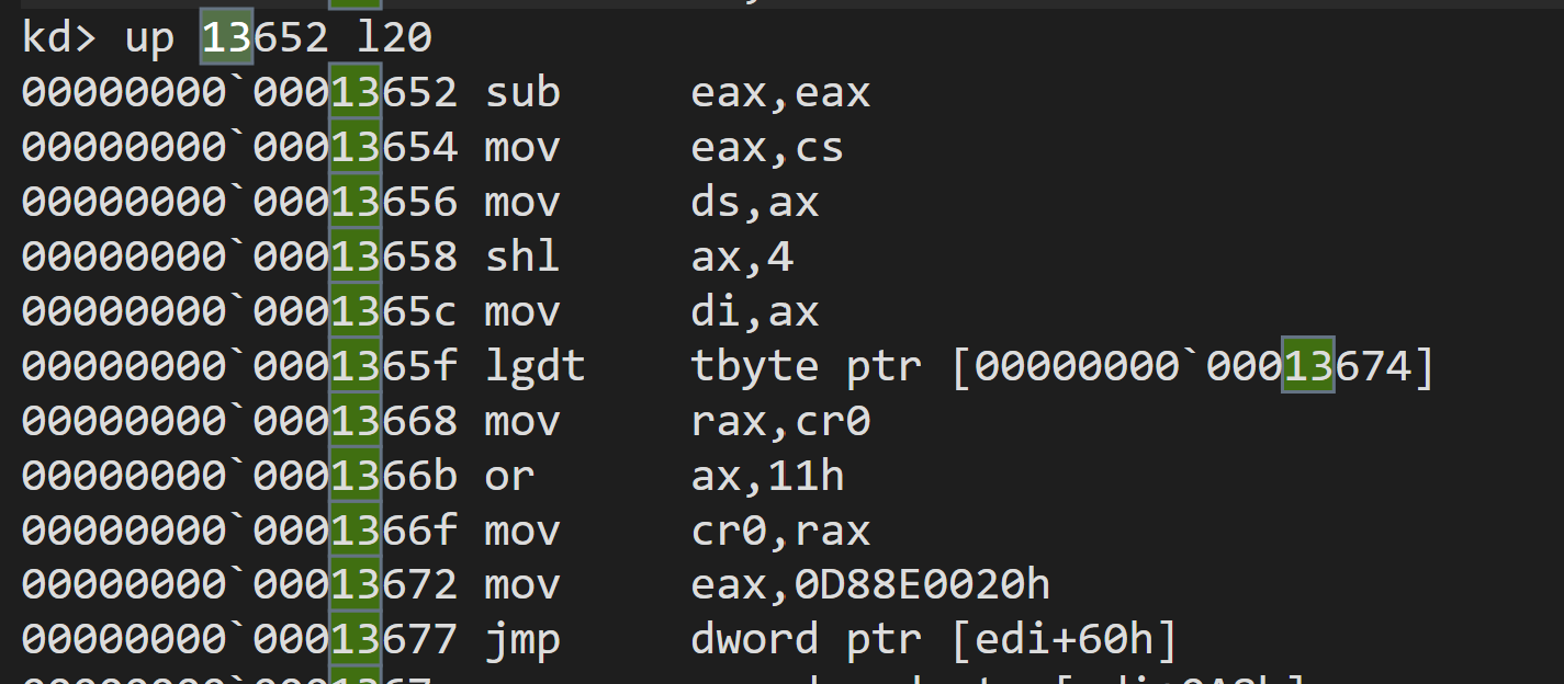
From code, the value of EDI is known to be 0x13000, because EDI is CS << 4, and CS is [19:12] of the IP, as stated in 8.4.3 (see the comment in the above pseudo code).

HalpPMStub - Protected-Mode 


Following EDI+0x60 navigates us to the protected mode stub implemented as HalpPMStub.

This code is responsible for switching to the long-mode. As seen below, it
  • sets CR4.PSE (0x1000),
  • updates IA32_EFER, then
  • sets CR0.PG (0x8000000), to activate the long-mode (see the second screenshot).


Then, it jumps out to where RDI+0x66 specifies. 

HalpLMIdentityStub - Long-Mode under Identity Mapping


The JMP leads to the short stub whose sole responsibility is to retrieve the value of CR3 that can permanently be used, that is, the same value as that of BSP.

As the processor should already working with the virtual addresses, let us switch to it.

RDI+0x70 gives us HalpLMStub.

HalpLMStub - Long-Mode


This is the final stub that APs go through. The first thing this stub does is to apply the permanent CR3 value to have the same memory layout as BSP (and any other already initialized APs) followed by invalidation of TBLs.

After switching the page tables, it performs various initialization, and at the end, it jumps out to where RDI+0x278 indicates.
This ends up with nt!KiSystemStartup, letting the AP run the same initialization code as BSP (except few things done exclusively by BSP).

Conclusion

We reviewed how Windows initiates execution of APs with the INIT-SIPI-SIPI sequence and how APs go though from real-mode to the regular NT kernel initialization function on Windows 10 19H1 without Hyper-V.
  
Hopefully, you enjoyed this post and gained more contexts on INIT-SIPI-SIPI VM-exits you may see while writing a hypervisor too.

Friday, March 13, 2020

Introduction and Notes on Design Considerations of UEFI-based Hypervisors

In this post, I am going to write up some of the lessons learned and the challenges I had to go through to write a UEFI-based hypervisor that supports booting Windows. I hope this post gives pointers to study and helps you get started with writing a similar hypervisor.
UEFI hypervisor brief design walk-through

Background


Lately, I spent some time to study EDK2-based UEFI programming and developed a hypervisor as a UEFI driver. It has been fun and turned out to be more straightforward than I initially imagined, but at the same time, there were some learning curves and technical challenges I had to take extra time to understand and overcome.

The major reason of taking extra time was lack of write ups or tutorials for my goal. Although there were few open-source projects and many documents and presentations I was able to study, those were not focused on UEFI programming with the context of writing hypervisors. This is entirely understandable as I do not suppose those are common subjects, and that was also why I wrote up this post.

In this post, I will start by giving a high-level overview of UEFI, and unique aspects in its execution environment, then look into challenges of writing a hypervisor as a UEFI driver.

UEFI Execution Environment


UEFI vs EDK2


UEFI is the specification of firmware to replace legacy-BIOS, where no standard exists, and offers a well-defined execution environment and programming interfaces. EDK2 is the open-source, reference implementation of the specification and provides tools to develop firmware modules.

Application vs Driver


Firmware modules can be built as part of a whole firmware image or as a standalone module (file) to be separately deployed. The latter is how I compiled the module. Additionally, UEFI modules can be written as an application which is unloaded from memory once its execution finishes, or as a driver which remains loaded unless explicitly unloaded. Obviously, the driver is the natural choice for the hypervisor, although I will mention the other common approach later.

Boot Time vs Run Time


The execution environment of drivers can be separated into two different phases: boot time and run time.

Frankly speaking, the boot time is before execution is handed over to the operating system and the run time is after that. This transition happens when a UEFI defined API called ExitBootServices is called. In the case of Windows startup, this is sometime before winload.efi transfers its execution to ntoskrnl.exe.

Most of the firmware drivers loaded on memory are unloaded at this point because most of them, for example, a network driver for PXE boot, are no longer needed once execution is handed over to the operating system. This type of driver is called boot drivers, and not suitable for the hypervisor that is meant to stay alive even after the operating system is fully started.

Runtime drivers, on the other side, are the type of driver that resides on memory throughout the system life span and suited for the hypervisor.

Boot-time Services vs Run-time Services


UEFI defines a collection of APIs, and their availability is impacted by the boot-to-run time transition. The type of API called boot-time services can no longer be used after the transition because drivers that implement the API are unloaded. After this transition, runtime drivers can only use the run-time services, which drastically reduces the ability of the hypervisor to interact with the environment.

Physical Mode vs Virtual Mode


Another transition that the runtime drivers have to go through is the change of the memory address layout.

At the boot time, the system is in the long-mode, same as Windows. However, virtual to physical address mapping is pure 1:1, that is, the virtual address 0xdf2000 is translated into the physical address 0xdf2000. This mode is called physical mode.

Soon after the transition to run time, a bootloader (winload.efi in the case of Windows) sets up and configures new page tables to map runtime drivers to the addresses that work well with the operating system (eg, the physical address 0xdf2000 may be mapped to 0xfffff803`1ce40000). Then, the bootloader calls the SetVirtualAddressMap run-time service letting runtime drivers perform their preparation, switches to the new page table and discards the old page table. After this point, the runtime drivers are mapped to only the new address, just like regular Windows drivers. This mode is called virtual mode. This transition can be catastrophic if the hypervisor depends on the physical mode page tables. We will review how it can be a problem.

Application Processor Start-Up


Another unique event that the UEFI hypervisor has to handle is processor initialization. Processors that are not selected as a bootstrap processor (BSP; the processor initialized first) are called application processors (APs) and are initialized after transitioning to the virtual mode. This is done by BSP signaling INIT and Startup-IPI (SIPI). When SIPI is signaled, APs start its execution on the real-mode and go through mode transition up to the long-mode (in the case of the 64bit operating systems). This requires some extra VM-exit handling that was not relevant for the blue pull style hypervisors.

Those unique aspects of the UEFI environment pose technical challenges and require different hypervisor design considerations.

Challenges, Solutions, and Considerations


Host CR3


As mentioned, the host CR3 becomes invalid if the value at the time of driver load is used because that would be physical mode page tables that get destroyed. The most straightforward solution for this is to set up our own page tables with the same translation as the existing one (ie, physical mode page tables) and use them for the host. This may sound complicated but is implemented with just 50 lines of C code in MiniVisor.

However, this results in having different address translations once the guest switches to the virtual mode and makes it significantly difficult for the host to interact with the guest. For example, host code cannot be debugged with tools like Windbg anymore because none of Windows code is mapped in a usable form while the host is running. If the hypervisor is going to need complex interaction with the guest virtual address, other approaches might make it simpler at the end. In a private build, I implemented a guest shell-code that runs in the same address space as the NT system process for interaction with the guest.
Injecting the guest agent that hooks Windows kernel API
It also makes it harder to access the guest virtual memory from the host for the same reason without implementing the guest-virtual-to-host-virtual mapping mechanism. MiniVisor implements this in MemoryAccess.c. This is essentially what every single hypervisor implements. 

Host IDT


For the same reason as the host CR3 is discarded, the host IDT becomes invalid if the value at the time of driver load is used. Although this does not cause an issue immediately because interrupt is disabled during execution of the host, any programming error causing exception will cause triple fault without running any diagnostics code. The solution is to create its own IDT for the host.

Having its own IDT, however, means NMI can no longer be delivered to the Windows kernel if that occurs during the execution of the host (reminder: NMI still occurs even if interrupts are disabled). MiniVisor discards NMI for simplicity but you should consider reinjecting it into the guest instead.

Host GDT


You may wonder about the GDT. Yes, the GDT also needs to be created, but also requires modification because firmware does not set up the task state segment that is required for VMX.

Logging


Console output API is the boot-time service that cannot be used after the transition to run time. Hence, console-based logging must be ceased after that point. This could be addressed in several ways, such as hooking into operating system logging API, but the simplest solution is to use serial output instead of console output. This has its limitations but requires almost zero extra code.

Another sensible option is to have ring buffer to store log entries, and later, let a client application to pull and print them out.

Testing Application Processors Startup


This requires the hypervisor to handle VM-exits as well as proper emulation of paging mode transitions that are not relevant for the blue pull-style hypervisors. Specifically, handling of INIT, SIPI and CR0.PG access are required.

For me, this was one of the most challenging parts of writing a hypervisor that supports booting an operating system, mostly due to lack of available virtualization solutions as a test environment and difference between them and the bare-metal environment (eg, TLB, MSR etc), requiring through testing with bare-metal.

My recommendation is to buy and set up a single-board computer with a serial port so you can at least do printf-debugging (or even better, Direct Connect Interface support). I might blog about selecting devices and setting them up.
Testing with a single-board computer

Driver vs Standalone File

Compiling the hypervisor as a runtime driver works as demonstrated in the project. However, the more common approach is to build the hypervisor as a separate file and a UEFI application loads it into memory and starts executing it. That is how VMware hypervisor as well as Hyper-V is implemented, as examples. The standalone hypervisor format is often ELF because of wider cross-platform compiler and debugging tool support. 

This approach has an advantage that the hypervisor code remains platform agnostic and re-usable; for example, one can write a small Windows driver as a hypervisor loader without mixing up platform dependent loader code and hypervisor code that should be platform independent. Then, the hypervisor module can remain portable.


MiniVisor did not take this approach just because of lack of structure started from experimentation. I plan to restructure the project in this way. 


Conclusion

We reviewed some uniqueness of the UEFI environment and how those impact design and implementation of hypervisors compared with those designed under the blue-pill model. We also looked at how MiniVisor was designed to work with those new factors and implied limitations.

While this short blog post may not be sufficient for some readers to have clear ideas of those challenges and explained solutions, I hope this post gives you some pointers to study the codebase of MiniVisor and help make sense of why things are written in different ways than the blue pill-style Windows hypervisor.

Further Learning

As a final note, if you are particularly curious about tooling hypervisor for research and/or just having a solid understanding of the underneath technologies and concepts, Bruce Dang and I plan to offer a 5 days class this October. This will let you write your hypervisor for both Windows and UEFI environments, develop "something useful" and play with them on physical and virtual machines to internalize technical details. 

Please sign up from this page or contact us if you are interested in.
https://gracefulbits.regfox.com/hypervisor-development-for-security-analysis